

DIY Power Bank | Portable Charger for Onewheel & E-Skate
Weighing in at about 7lbs, this can charge a Onewheel XR about 1.25 times. No need for an outlet.
IF YOU DO NOT HAVE THE KNOWLEDGE OF, AND COMFORT IN SAFE BUILDING PRACTICES, DO NOT PROCEED. BUILDING AND WORKING WITH LITHIUM-ION BATTERIES IS POTENTIALLY DANGEROUS AND CAN LEAD TO SEVERE INJURY AND DAMAGE.
The year 2020 was difficult for everybody, for a variety of reasons. However, one small issue that arose this year in New York City was that available charge spots became very scarce, and indoor charging at places like coffee shops and restaurants were no longer a viable option. Gone are the times now that you can walk into an eatery, order a coffee or snack, and sit with your board plugged in for an hour to recharge. Similarly, many outlets in parks and on the street have either been shut off, or their breakers tripped with no hope of them being restored anytime soon.
What is someone to do? Well, internal extended battery modifications are all the rage at this time, with Onewheel owners replacing their stock battery packs with higher capacity builds. This is a good solution for many, and it certainly has its value. However, Future Motion (the folks who build the Onewheel), have continued to lock down their board’s ecosystem in order to prevent internal modifications. This leaves newer buyers of Onewheels stuck with their stock battery capacity, and generally only with the option to use a fast charger when they’re out and run out of power.
Personally, I’ve been on group rides where the following situation is bound to happen: several folks find a charge spot, everyone takes out their fast charger, and plugs into to a power strip plugged into an outlet. You now have several boards charging at 6+ amps, and a few minutes later, the outlet shuts off. Everyone got about 3% charged, and the guys with fender contraptions all over their board are riding off saying “stock range is so 2018!”
To avoid that, one would want a portable charger; a power bank. Similar to a portable power bank for a phone or tablet, one can have a portable power bank for their Onewheel or electric skateboard.
To be clear, this is NOT an original idea. At all. In fact, it’s important to take a short walk down Amnesia Lane and see what came before us. Going back a few years, the earliest popularized version of a portable power bank was made by the company CarvePower (https://carvepower.com/) and I had seen this setup on the Corridor Crew YouTube channel, used by famed Onewheel enthusiast Wren:
CarvePower’s setup used hoverboard batteries (10s2p configuration of 18650 cells) running through a solar charge converter to output the needed voltage and amperage to charge the Onewheel. By the way, charge voltage of the Onewheel is 63 volts, at either 1.2 or 3/3.5 amps for the Pint, and 3 or 6 amps for the XR. The charging specs for the V1 and Plus are 58.4 volts at 3.5 amps (for fast charging), and you could set it to do that as well. It was a cool setup, since you could put batteries in your backpack and not worry about finding an outlet.
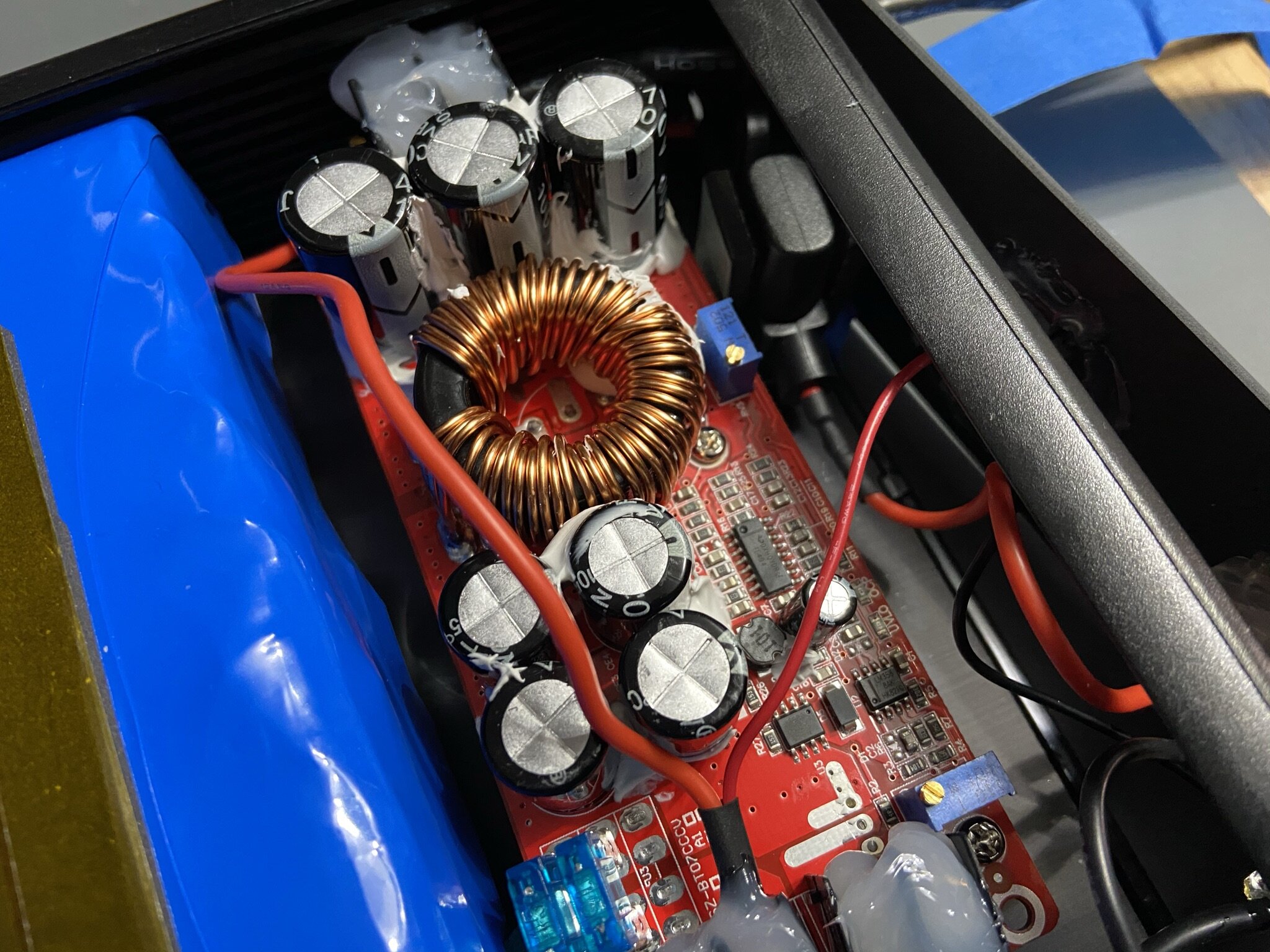
At some point, CarvePower switched from using the solar charge converter to using a commonly available DC to DC Boost Converter, which you can see in their manual, available here. That converter is actually at the heart of most current builds that offer portable charging, as it’s a relatively inexpensive part that can be widely adjusted.

Can be found as a “1200W DC to DC Boost Converter” on many sites.
After this, a number of different charge options showed up as DIY builds and projects that all more or less encompassed the same idea.
Skipping ahead to the more direct inspiration for this project is the Board Bank from ChiBattery Systems (https://chibatterysystems.com/boardbank). It takes the Carvepower-esque idea and changes the form factor to use a custom built battery and puts everything into a single enclosure. This makes it look and feel more like a portable charger / power bank for your phone or tablet, which is a very clever and elegant way to go about it.
That all being said, let’s get into the build.
PARTS LIST
Battery Pack
28 High Capacity 21700 Cells; I’m using Samsung 50e, but you can find 50G, Molicel M50a, or LG M50 cells. These can be found at reputable sellers like Li-Ion Wholesale, 18650 Battery Store/Bulk Battery, or IMR Batteries. I recommend getting a couple extra cells in case you get one that’s DOA or you end up making a mistake and damaging a cell.
7s BMS Circuit Board; I’ve had good luck with the generic BMS you can find on eBay, AliExpress, or Amazon. Just make sure it fits the sizing, and has a balancing function.
Nickel Strips; I tend to use 0.2x10mm nickel strip, since it carries the current needed, and is weldable with my Malectrics welder. 0.15mm thick nickel is easier to weld, but obviously doesn’t carry as much current.
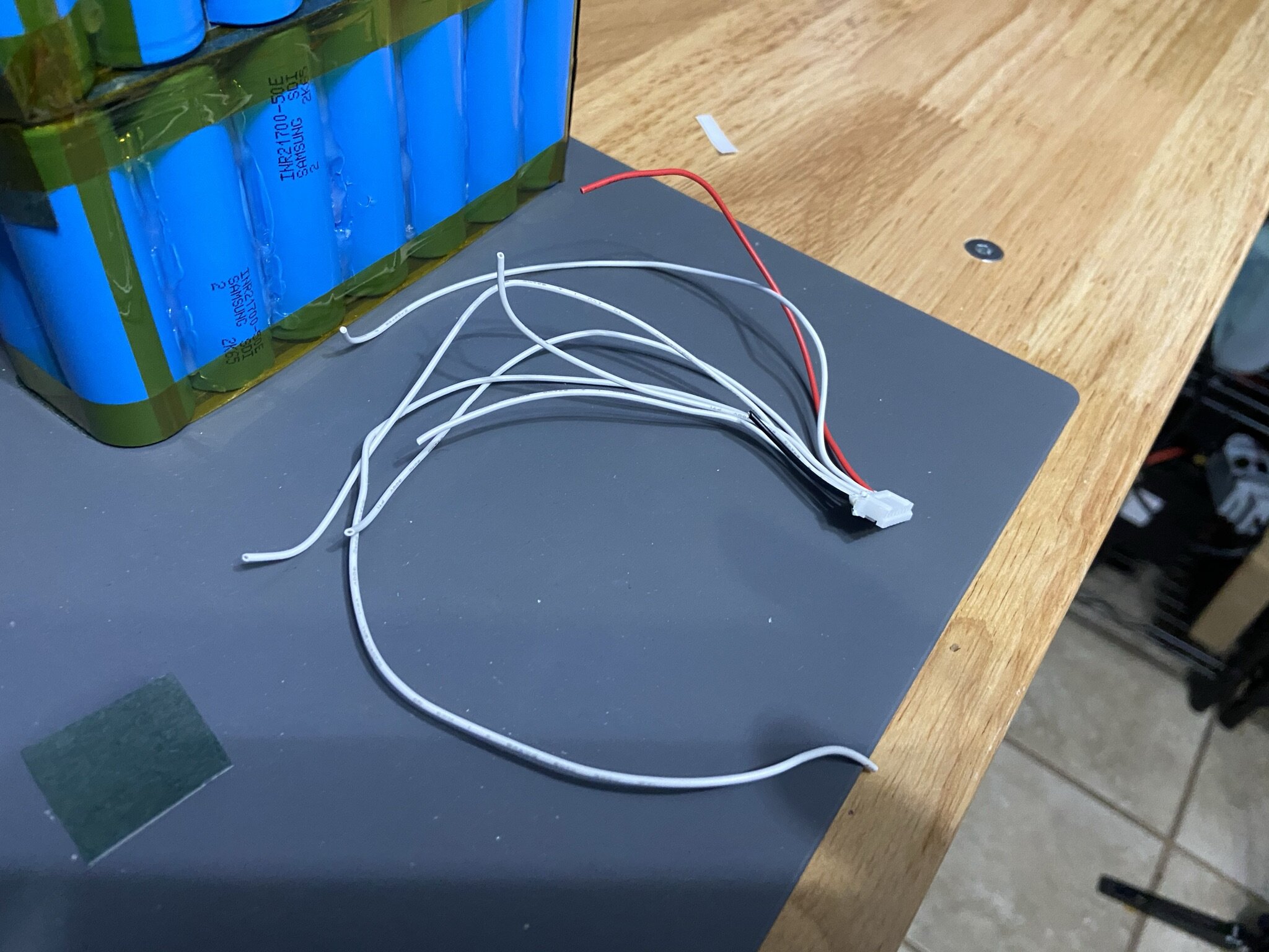
Wiring; For this build specifically, I’m using a combination of 14 and 18 AWG silicone wire. This is easily found online, and 14 AWG accomodates the types of current this specific build experiences without being too bulky.
Kapton Tape; I use a mix of 1”, 1/2”, and 1/4” tapes depending on the location and need.
Fish Paper; I get this from Amazon, made by 145PTAGS.Com. I use the adhesive backed paper, and it’s fantastic.
Fish Paper Insulation Rings; These are for the positive terminals on the cells. Absolutely necessary.
Fiberglass Filament Tape; this is the stringy looking tape that helps with structure and support. It insulates decently also.
PVC Shrink Wrap; For this build I use 180mm wide PVC, specifically blue. This is the final wrap for the pack once it’s finished.
Case and Internals
1200W DC to DC Boost Converter; This is a generic voltage boost converter, and can be found on Amazon, eBay, and AliExpress. It’s not actually a 1200W converter, but it does work decently for our purposes. Size should be about 130x52x53mm. This is the one pictured earlier in the article.
Gardner Bender GSW-124 Electrical Toggle Switch; There are some conflicting specs on the current rating, but the official page specs it where we need it for this build.
GX12 2-Pin Male Connector Plug; This is the charge port, and ideally you’d have the female companion plug for your charging device.
JS-8T Battery Voltage Indicator; Also available on eBay and AliExpress, this is programmable and needs to be configured for the 7S battery. The best guide I’ve found for configuring this meter is here:
Automotive Fuse Holder & Fuses; These go on the charge line, as extra protection before the BMS.
2-Core Power Cable Wire; This is for the output cable, and it’s two 18 AWG wires inside a cover. The one I used was “18 awg 0.75mm² Silicone Electrical Wire 2 Conductors Cores Wire” on Amazon.
Output Plugs; For the XR it’s an XLR female, for the Pint it’s a GX12 2-pin female. Otherwise, you’ll need to find the appropriate connector for your board.
Thermal Glue; I’ve had good luck with the “Halnziye 10Gram Thermal Conductive Glue” on Amazon. You want a thermal glue that hardens and forms a strong bond, since this both adheres the converter to the case, and transfers heat between the two. I’ve tested other glues, and this works well.
Neutral Cure Silicone; I use either the electronics grade silicone found on Amazon, or I go to a hardware store and get the GE Slilicone 2 clear tubes. So long as it’s neutral cure, you should be fine. This is good insulation coverage for the input and output terminals once everything is wired up.
Silicone Conformal Coating; I like using this as a once or twice over coating for parts that I can’t practically insulate with heat shrink tubing.
Equipment and Tools
Multimeter; More important than most other tools, you should really have a multimeter. Checking voltages and checking polarity are VERY IMPORTANT. Again, you should know what you’re doing with regard to basic DC electricity conventions. Not knowing the basics is what leads to dangerous mistakes.
Spot Welder; This is the kicker. Most folks see this as the main investment in battery building, and often times it is. I personally use the Malectrics Welder with a car battery (which I bought new and keep charged for this purpose). Others use the KWeld. There’s also a new Flipsky branded welder that seems decent enough. Either way, you’ll need to sort out the spot welding situation as well as the power source that powers it. Don’t skimp here. Soldering nickel strips to cells isn’t a good idea.
Soldering Iron/Station; I personally use a KSGER T12 station, and it works well. It’s important to have an iron with appropriate tips, and enough heat flow to do large solder flows quickly. The faster your soldering work can be, the better. Also, get good flux. Don’t skimp with that either. No-clean flux is best, but flux is very helpful in avoiding bad soldering joints.
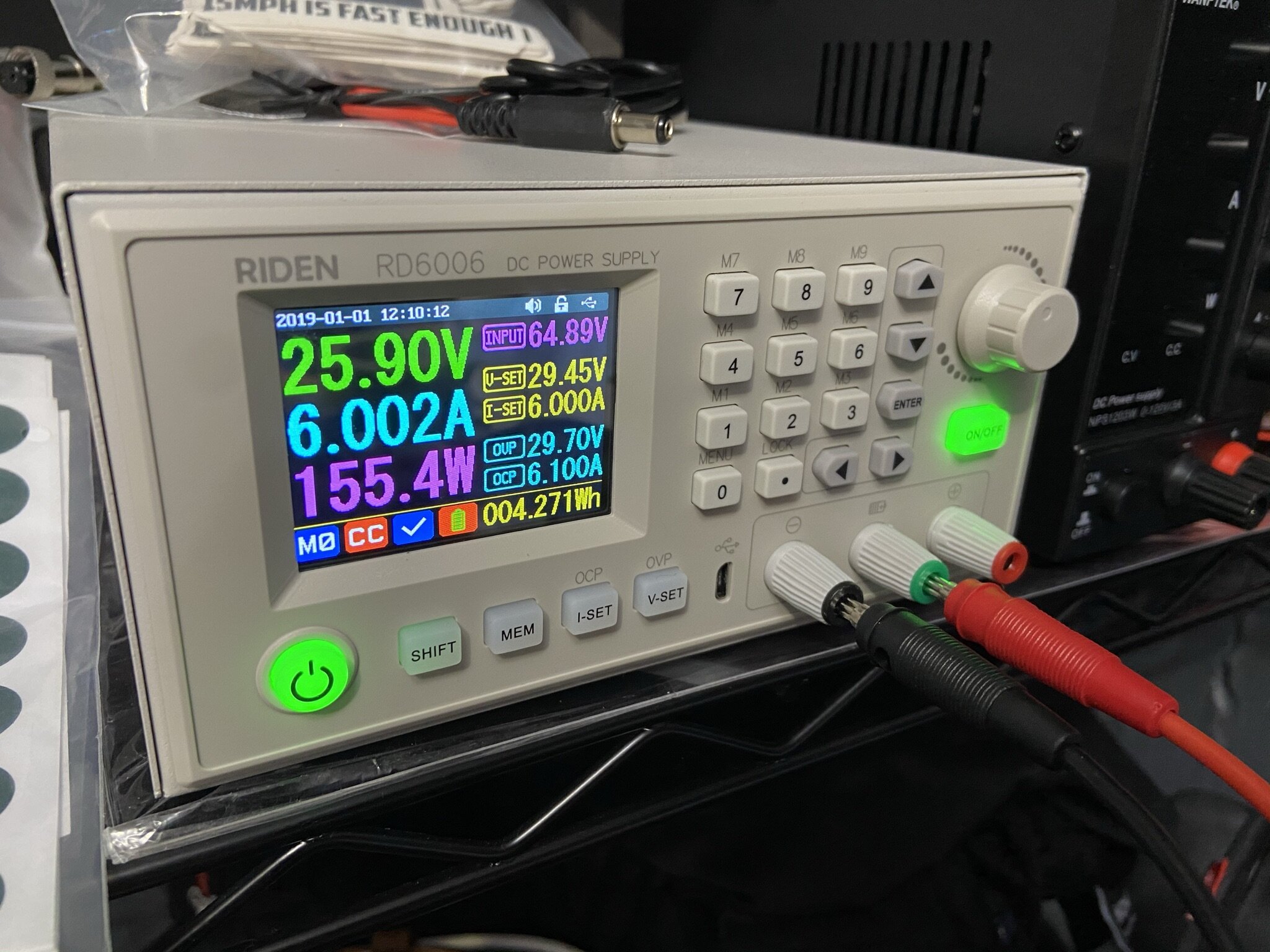
Bench Power Supply; This is also, very important. If you’re going to work with batteries at all, it’s good to have an adjustable benchtop power supply. I use the Riden 6006, which came as a kit and doesn’t cost much. It’s adjustable up to 60v and 6a. So, charging this power bank at 29.4v/5a is not a problem, since I just have to create the appropriate charging cable. This is a power supply I use to charge almost everything I build. Otherwise, you’ll need to source a 29.4v/5a charger.
Scissors/Shears; After building several batteries, it became clear that some of the most used tools on my workbench are scissors and shears. Shears help cut nickel strips (although I use a guillotine to cut the strips off the roll), and scissors cut tapes and fish paper. I use Heavy Duty Fiskars shears, a set of standard 3M scissors (that came in a pack with some Dual-Lock), and a small set of detail scissors.
Pliers/Wire-Strippers; I mostly use a pair of spring-loaded precision pliers that came in a pack with flush cutters, made by Crescent. I’m a bit of a fan of pliers, and have more than most peope would need. But precision pliers are great for many things, including holding hot wires down when soldering. Wire-strippers shouldn’t need an explanation.
XACTO/Art Knife; This has come in very handy many times. I use it to strip wires, cut insulation, manipulate small parts, spread adhesives, spread paste flux, etc.
The Build
ONCE AGAIN, IF YOU DO NOT HAVE THE KNOWLEDGE OF, AND COMFORT IN SAFE BUILDING PRACTICES, DO NOT PROCEED. BUILDING AND WORKING WITH LITHIUM-ION BATTERIES IS POTENTIALLY DANGEROUS AND CAN LEAD TO SEVERE INJURY AND DAMAGE.
Now, this IS NOT A GUIDE ON HOW TO BUILD A BATTERY. This is just a set of specifics on how I configured this particular battery to fit in this build. You should be familiar enough with safe building practices that this information is familiar to you, since all I’m doing is guiding you through my own DIY build.
As far as I’m concerned, this is ESSENTIAL reading before you start ever building a battery (and yes, ALL of it):
https://forum.esk8.news/t/the-battery-builders-club/720
Also, this is very good viewing:
^There is also a Part 2 to Lee’s video, so watch that as well.
Moving on, let’s talk about the battery. This is a 7s4p brick shaped pack, made up of Samsung 50E cells. The prototype I built myself actually uses rewrapped Samsung 50G cells, since they were on sale at the time. Funny story…I actually built the first pack for this project entirely wrong, and ended up destroying some cells in the subsequent teardown. So, that whole pack ended up recycled. T’is the cost of learning.
You can use any of the high capacity, lower discharge class of cells though, from the 50E/50G, to the Molicel M50a, to the LG M50. These cells all have a roughly 5,000mAh capacity, and work well for a power bank without a high discharge demand. I recommend the 50E because it’s relatively inexpensive, and usually not the hardest to get. But generally, one has to always compromise.
For cell connections, I used 0.2x10mm nickel strips, since they more than cover the amperage needs of this build, and 0.2mm thick nickel can be welded with my Malectrics welder. The pattern of nickel is fairly conventional, with standard parallel and series connections made across the parallel groups. The parallel groups themselves are made up mostly of squares of 4 cells.
The exception is the middle parallel group, which has to be split up across the fold over. Since the pack has to be folded in half to form the brick shape, there are two cells whose negative terminals span the fold, and whose positive terminals need to be bridged/jumped from one side of the pack to the other.
This may sound confusing, but once you look at the photos, and see the fold in the video, it will make sense. And, make sure this fold layout DOES make sense before you do it.
YOU DO NOT WANT TO MISTAKENLY BRIDGE THE WRONG ENDS AND END UP SHORTING SOMETHING.
The images should be in build order, so feel free to browse through them.


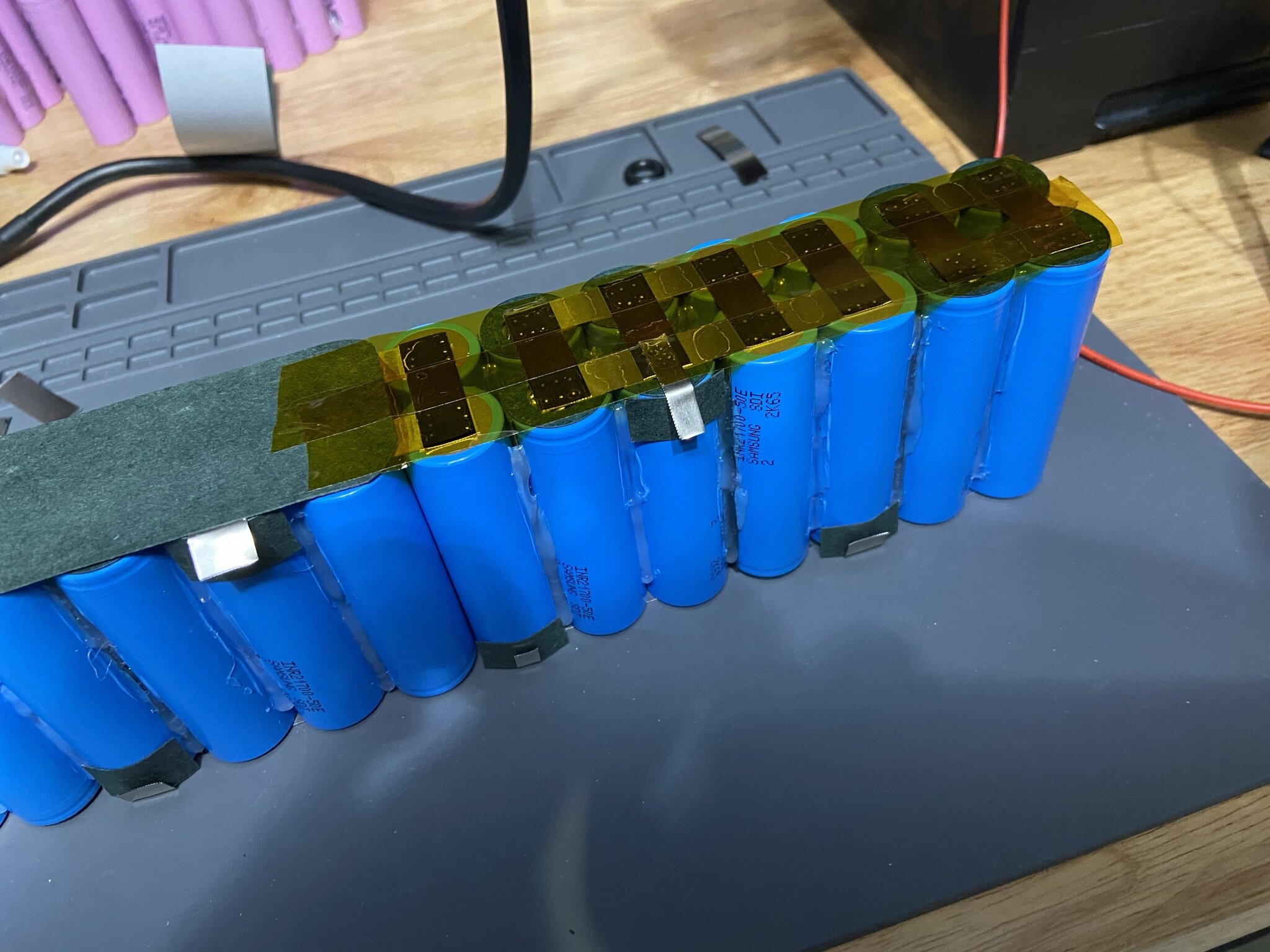
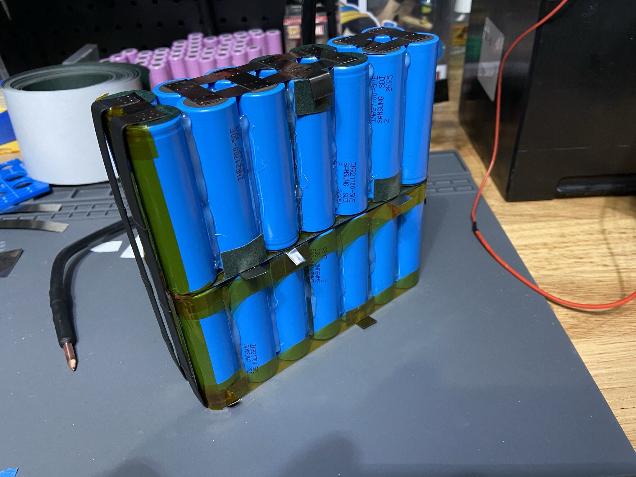
Note that the parallel groups are insulated with fish paper, and the positive terminals are insulated with fish paper rings. The bridging of the middle parallel group is done here by long pieces of nickel strips, covered in shrink wrap through the bends onto the cell terminals. Also, there is fish paper and Kapton tape below those two jumper strips.
I think of it as there being a regular parallel group of 4 cells, but on one side, the connecting strips are stretched out.
You’ll also notice that I leave those connections for last, since I’m doing insulation and other welding work on either half well before it has to be welded together and folded.
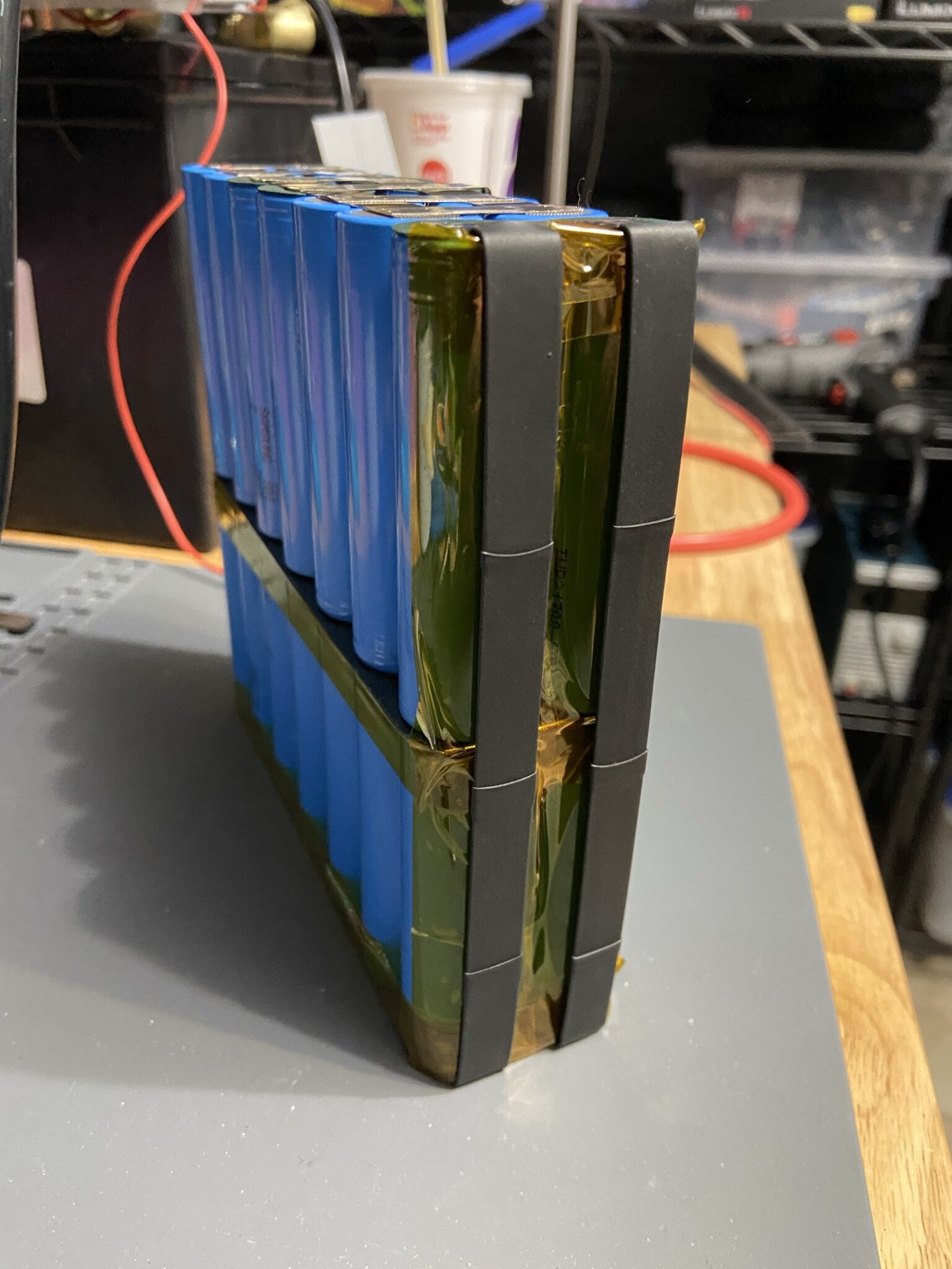
Once that is all done, it really is a matter of making sure there are adequate balance tabs in place, fish paper underneath them as well as where they fold, and then setting up the wiring for the BMS. As was mentioned in the parts list, this is a fairly generic 7s BMS board, and I’ve had good luck with it. I take the heatsink plate off, since it’s not needed for charging. There isn’t much heat generated during charging and balancing, and the discharge doesn’t go through the BMS.
For discharge from the battery going into the converter, it’s just a direct line from the positive and negative terminals of the battery pack.
After a charge test, it just gets wrapped in two crossing layers of blue PVC heat shrink.


Moving on to the rest of the build, it’s actually fairly straightforward. The real tricks mainly have to do with placement of all the parts and making sure everything fits together as it needs to. You have some space to play with, and so this isn’t that daunting a task.
One tip I mentioned in the build video is to use a spreader to open the case a bit so you don’t damage anything when sliding the battery pack into it. Once the battery pack is in, I used the rear plate to help space everything and make sure that the foam added to the battery afterward would compress properly against the back of the case and the edge of the voltage converter.
The voltage converter itself needs a bit of preparation (again, as noted in the build video), so here are the steps I took:
Since the heatsink couldn’t easily be removed, I sealed off the holes in the heatsink with silicone.
Once this was all cured, I taped off everything around the heatsink to seal off the underside of the circuit board.
Using a table sander, I evened out the bottom fins of the heatsink so it sat a bit lower and more evenly against the inner surface of the enclosure.
I used an air compressor to clean all of the aluminum dust off of the converter and made sure that it was spotless before removing the tape and testing it again.
I highly recommend you go this route. It ensures that the mating surface of the heatsink is even with the enclosure, the adhesive bonds properly, and heat transfer is optimized.
Once that is done, you need to make sure of the placement of the converter in the enclosure, and then apply the thermal adhesive along all of the fins of the heatsink. Then VERY GENTLY clamp it down in place and make sure it doesn’t move. It’ll take a couple hours to set, but give it at least 24 hours to fully cure before moving anything or wiring anything.


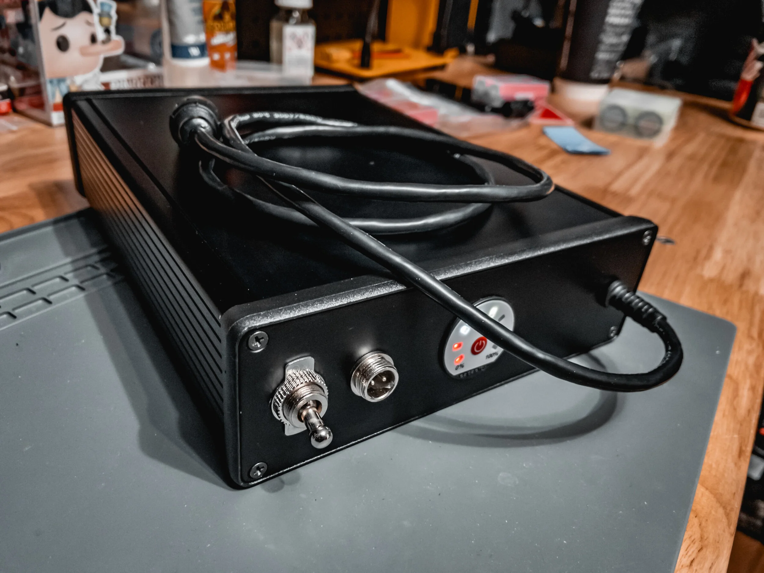
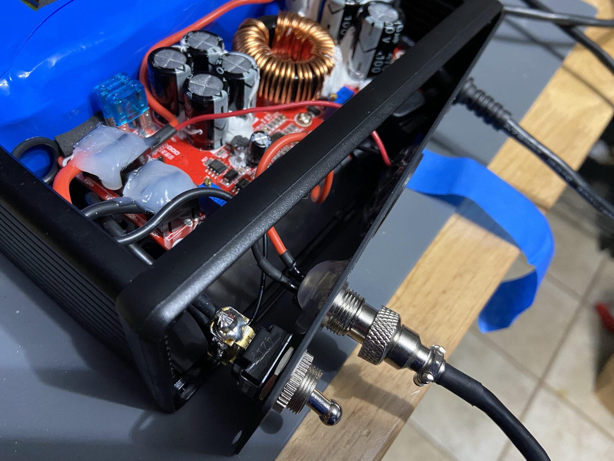
Before you glue down the converter, it’s important to get the spacing right not only with the battery, but also with the ports and wiring on the front panel. Pay attention to the charge port, and where the wiring goes relative to the left-most blue potentiometer. It’s a bit tricky to make work.
I used a step drill bit for the ports on the front, having measured the diameter of each part, and where on the faceplate I wanted it to sit.
Now…I apologize for this, but I actually ended up taking the measurements for the front panel in both imperial and metric. I’m sorry. Below are how I laid it out:
Main Switch: 5/8” from left edge, 12mm hole
Charge Port: 1 1/2” from left edge, 12mm hole
Capacity Meter: Centered, 28.5-29mm hole
Output Cable: 5/8” from right edge, 8mm hole
I covered the front panel in masking tape to prevent scratching, and also drew up a quick jig to help hold the plate while drilling. The large center hole is the hardest to do, and it’s when you really need the jig. I 3D printed it in regular PLA, and made it tall enough to allow the large step bit to go all the way through and also catch the aluminum shavings. It takes a while to print, and uses a decent amount of filament, but I think it’s a very useful jig.


With that taken care of, the task of wiring up the panel can be done.
The main discharge of the battery goes as follows:
Main positive goes into one of the screw terminals (+) on the converter.
Main negative goes into the bottom of the main switch. Top of the switch then goes into one of the screw terminals (-) on the converter. Leave switch off, for obvious reasons.
Charge negative from the pack (smaller wire that goes to the BMS), goes to the charge port (pin 2).
Charge port positive (pin 1) goes to the fuse holder, then into one of the screw terminals (+) on the converter input. This will connect it to the battery pack’s positive.
The capacity meter has its positive wire going into the same positive screw terminal (+) as the charge port positive, and the negative wire going to the BOTTOM of the main switch, so it can detect voltage independent of the main switch. Refer to the pictures below.


Once everything is soldered, I used shrink tubing, silicone, and conformal coating to insulate everything up as well as possible.
Getting the output cable wired in on the right is a bit of a trick, since there’s limited space there, but it’s not too bad.
As was mentioned above, it’s a great idea to keep the switch “OFF”, while doing all the wiring. Conveniently, this allows you to connect the main discharge wires to the input terminals of the converter and not have any sparks while connecting everything else.
Before closing everything up, I put strips of 1/4” thick neoprene foam (adhesive backed) on the top and bottom of the battery, on the corners against the sides, and around the fuse holder to keep it from rattling around.
Configuring
Setting the output values on the voltage boost converter isn’t THAT tricky, but there is a bit of a catch to it.
Voltage is east, since you can just use a multimeter to measure that on the output.
Current (amperage) however, is a different story. What you’re actually setting is the current limiter, since current is drawn by the device being charged and not pushed by the charger. So to set this limiter, I use my electronic load generator, and set it to my desired current limit. I then lower the potentiometer on the converter until the voltage drops down from the preset voltage. So if I’m sinking 5 amps at 63 volts, and while I’m lowering the limiter the voltage drops out, then I know I went just below that 5 amp limit. Then I raise it a tiny bit, slowly, until the voltage comes right back up to the 63v. That’s generally where I leave it.
It’s not perfect, I’ll admit. Another way, is to back out the limiter all the way so it’s almost 0, and then hook the output wire up to the ameter/voltmeter box I showed in the video through the shunt resistor. Then, hook it up to your board and start charging. It won’t send any charge current, so then you’d slowly turn the potentiometer until you saw the desired amount of current being drawn through the ameter. That’s a more accurate way to set it, but it requires more wiring and time, and I’ve gotten good results using the electronic load.

After that, test it. And test it again, and then test it again.
Honestly, I don’t think I ever really “use” any project I finish. They just undergo extended testing.
Anyway, please heed all warnings, and proceed carefully if you choose to build this. Best of luck, and stay safe.
Oh…and you can make a half-sized version of this. I made one for a friend, but I don’t really advise it. The current needs aren’t well met by a 2p setup, and the voltage sags enough to lead to a less than ideal setup.
