
Floatwheel: DIY One Wheel Build

If you’re reading this, it means you’ve seen my video (and hopefully, video series) on this DIY kit, and want to learn more. Or you have one and need some help with the build. I will try to keep this article as useful and top-driven as possible, since I’ll have left my opinions on the kit itself to the last video in the series. That being said, let’s get to some context that I touched upon in the video.
What is a DIY Onewheel?
Well, firstly, it’s not a Onewheel. It is actually kind of important to realize that “Onewheel” is a specific product, made by Future Motion. This is good to keep in mind, since when Future Motion’s marketing material says something like “inventor of Onewheel”, it’s technically an accurate statement, even if it isn’t in spirit. That is to say, that the self-balancing one-wheeled skateboard/hoverboard type device pre-dates the actual Onewheel. Is that important to this project? Not really, but it’s worth mentioning. We’re all on a journey of learning, and so it’s good to pick up bits of trivia here and there to keep in our minds for when it may become useful.
Moving on, what is this thing? How does it work? Can I build it? Should I even care?
To take an excerpt from my video script:
A Onewheel is a self-balancing electric skateboard. And it doesn't function ALL THAT DIFFERENTLY than other PEVS (personal electric vehicles), really. Fundamentally, something like this works off a battery, feeding power into a motor controller, that sends power into the motor. In an electric skateboard, the motor controller gets its input from a remote. In a Onewheel-shaped board, the motor controller gets its input from a balancing circuit. It senses angles and movements, and uses that to control the motor, which then does everything from keeping you balanced to moving you along.
Electric Unicycles are fundamentally the same.
What we have here is a battery, into a motor controller, into a motor. This motor controller is based on an open source project called VESC. And you can configure it to work any way you want it to, within certain parameters. It has a balance circuit, and you can configure that in the software. The code for the balance circuit was actually written by a gentleman named Mitch Lustig, and you can find him and his tutorials here on YouTube. I'll link to it below, it's really interesting stuff and explains A LOT about how these systems work.
This is all good to keep in mind, because the Floatwheel isn't the only game in town. There's also the Fungineer's Funwheel, which has been around a bit longer. And now, there's a growing community of people who are working on replacing Onewheel internals with VESC based parts, in order to be able to configure them however one would want. I, fortunately, am one of these people.
Benjamin Vedder is the person behind the VESC Project, by the way, and you can find it all at https://vesc-project.com/
If it weren’t for Vedder and the VESC Project (as well as all of the beta testers and contributors who have been working on that project for several years), this board, and almost every high-end boutique electric skateboard wouldn’t be possible. Neither would DIY electric skateboards for that matter. I want this to be said, because the project is the heart behind so much in the PEV space, and it’s astounding the things that are possible because of VESC. It has gone far beyond a way for DIY builders to make electric skateboards (which I still enjoy doing), and is leading to a growth of a community of balance vehicle builders that will soon (hopefully, at least) color the landscape with options and tools to make the boards we ride better.
The Floatwheel Kit Itself
So, as per the first video in this series covers, you have to sort of put the whole thing together yourself. At least, for the most part. The notion that it’s a “kit” is technically true, and the parts you get are well collected and make the build more convenient. That’s not to say that the Floatwheel isn’t without problems… It is actually littered with problems. Many of them have workarounds, and some do not. What’s kind of encouraging is that the Floatwheel Discord server is full of people who have actually contributed time and effort into making this kit more enjoyable, easier to assemble, and very much rideable. It’s because of that community that the Floatwheel is as viable an option as it is, really. I myself am very grateful to the Discord server members for helping with the build, and with providing alternative parts and methods to this build.
As is often the case with community-centric projects, it is the members that end up taking it and bringing into a new light that can benefit all involved.
In the interest of covering as much ground as I can here though, I will highlight my first installment of the video series, and then go on to write out the issues I ran into and how I worked around them.
Part 1: Assembly
Putting this kit together isn’t the hardest thing in the world. However, if you’re not generally into DIY projects and/or you haven’t built something like an electric skateboard or e-bike before, then it’s import to take the time and familiarize yourself with how PEVs work, as well as to generally prepare yourself for what could be a very frustrating journey into assembly. I can only really speak for myself, but before I touched this kit, I had already collected an entire small workshop’s worth of tools and materials from building boards and batteries, and had already made the early beginner mistakes when it comes to the steep learning curve of DIY electric boards.
I followed along with the assembly video on Floatwheel’s YouTube channel, and it was helpful in getting started. What my own video tried to incorporate was just a few bits of information that I learned while putting it together. All told, I spent about two days worth of time building the kit itself, going fairly slowly and making sure I didn’t break anything along the way. When it comes to dealing with lithium ion batteries, wiring, and potentially dangerous electricity, I don’t tend to go about anyting casually. And neither should you. A damaged wire or sliced insulation during a botched assembly can be catastrophically dangerous.
DO NOT TAKE ANY DIY PROJECT LIGHTLY. MINIMIZE YOUR RISK BY TAKING IT SERIOUSLY
So, here’s the calibration video that you should watch and follow along with before assembling the controller into the board:
That’s how I calibrated my IMU (inertial measurement unit), and it has proven to work well so far. Keep in mind that should you ever update or reinstall firmware on your VESC controller, you’ll have to redo calibration and all the rest of the settings.
Moving on to the assembly, this is the video from the Floatwheel channel that I used while putting my board together:
DO NOT USE RED (PERMANENT) LOCTITE OR THREAD LOCKER ANYWHERE ON THIS BUILD.
Use blue/purple, or medium strength Loctite or thread locker. If you use red/permanent thread locker, you’ll need high heat from a torch or similar equipment to be able to remove the fastener. This means adjustments and repairs will be near impossible, if not entirely impractical. Stick to medium strength.
There are many cuts in the video, and to be perfectly honest I had to pause that video A LOT in order to proceed with a segment of building. Often, I would skip backwards in the video and rewatch parts to make sure I got it all right. Generally, my learning curves are pretty steep, and so I usually need a lot of repetition and instruction before I can do something cleanly on my own. Many don’t need as much prep as I do, but this is just something to be aware of.
Noteworthy Issues and Fixes
There are only a few things that I didn’t get to document in the video that I do think are worth mentioning.
Since this kit uses Onewheel Pint bumpers, it also does kind of fit a Onewheel Pint Float Plate. I had an extra Float Plate Solo, and so I installed it onto the bottom of the Floatwheel. It does take some modifying to get it to line up perfectly, and you do need to source longer screws to get everything together. However, since the bumpers themselves are actually what house the front electronics, AND the light bars are installed directly into the bumpers also, it seemed a good idea to add some wear protection. I do a lot of tail drag stops, and I didn’t want to wear down an entire assembly in a short amount of time.

Also, when I got the motor, the motor phase connectors were corroded and greenish. It looked like they used some lower quality brass plugs, and so I just changed those out to higher quality banana connectors. The motor and Balance Pro controller use 4mm banana plugs, but the ones I soldered in were a slightly different style that actually hold together a bit more snuggly than the ones that were originally on there. I show a clip of this in the video, but I don’t talk about it.

Next, I rewired the connections between the front and rear compartments. The stock Floatwheel battery has a common charge/discharge plug, and the smaller plug is for the e-switch on the BMS to turn the battery (and then the controller) on. I wasn’t running it this way, and so I had to rewire things. Since I built my own battery for this, I wired the battery’s BMS for charge only, and connected it directly to the VESC for discharge. This also meant that I had to use an anti-spark switch for the on/off power switching, which I placed in line between the battery and the VESC.

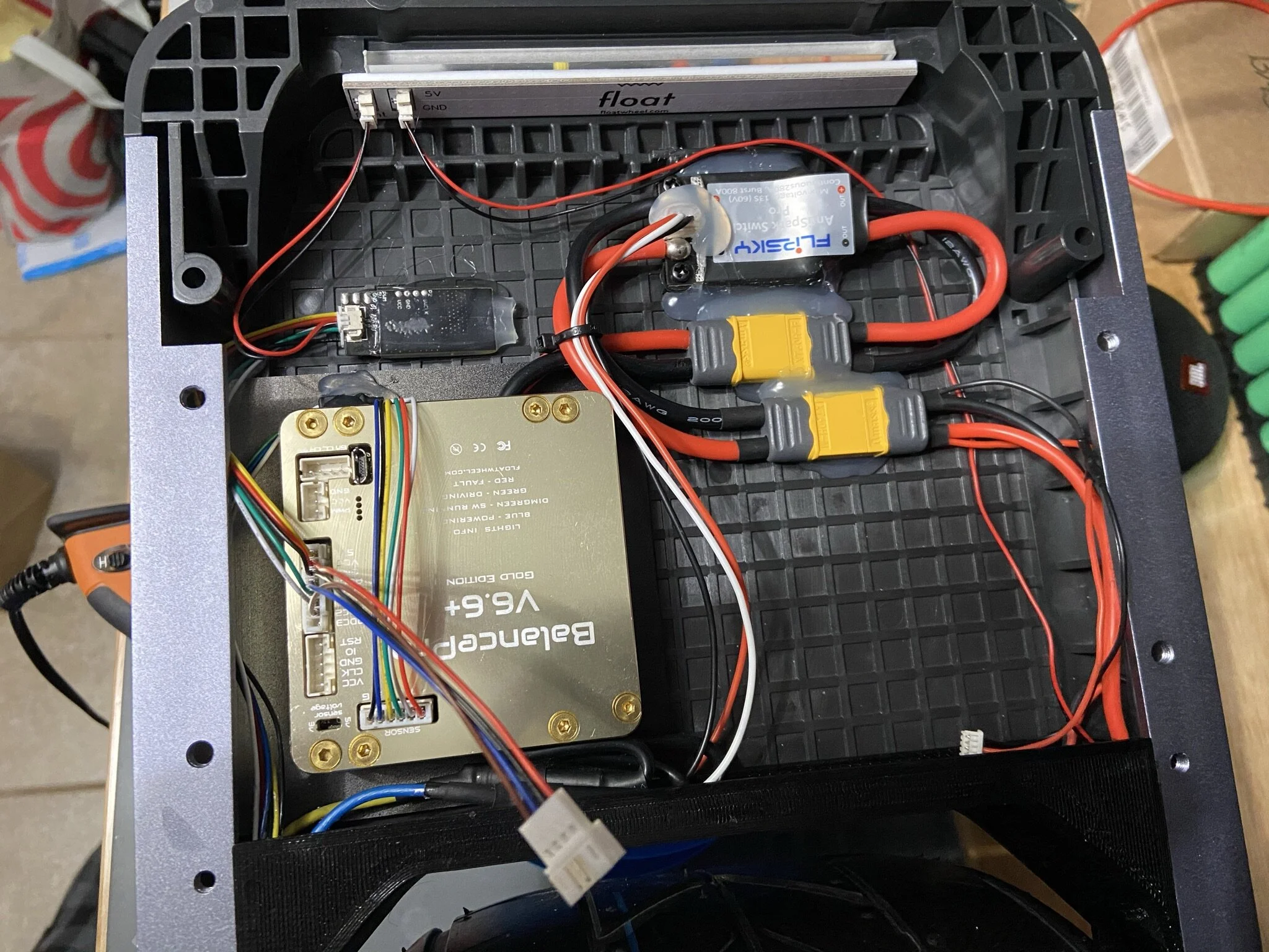


Part 2: Software Configuration
This video shows the process from configuring the motor settings to setting the values in the Balance App section of VESC Tool:
Important Settings:
Please note that these are NOT perfect settings, but just the settings I currently have. When newer versions of the firmware are released, I will add updates to this article AT THE TOP, so that they can be easily seen.
Below are some of the important settings values that I have currently with this controller:
MOTOR CONFIGURATION
Motor poles - 30
Gear Ratio - 1
Wheel Diameter - 270mm
Motor temp sensor is 100k
IMU CONFIGURATION
Sample Rate - 1,000Hz
Mode Mahoney
Accel Confidence Decay - 0.1
Mahoney KP - 0.38
Offsets
Accel Offset X - 0
Accel Offset Y - 0.010
Accel Offset Z - 0.015
Gyro Offset X - 0.640
Gyro Offset Y - 1.450
Gyro Offset Z - 0.300
Gyro Offset Clamp - 5.000
BALANCE APP CONFIGURATION
PID - 6/0.0050/810
D Term PT1 Filter
Startup
Roll Tolerance - 20 deg
Startup Centering - 30 d/s
Brake Current - 10 amps
Tiltback
Speed - 10 d/s
Duty Cycle - 0.75
HV Tiltback - 60v
LV Tiltback - 40v
Constant Tiltback - 0.5 deg
Fault
Duty Cycle Cutoff - 0.95
Duty Fault Delay - 500ms
ADC Switches
ADC1 0.08v
ADC2 0.80v
Half Delay - 500 ms
Full Delay - 300ms
ADC Half State Fault - 600 ERPM
Again, these settings will change in the future, when revised firmware is released